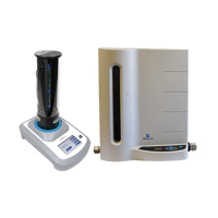
Proven Precision Gas Flow Measuring Tools And Technology
Measuring gas flow can be complicated. DryCal gas flow calibration equipment directly measures volumetric flow – regardless of gas species. Accredited by ISO 17025 and NVLAP of NIST, our equipment and software lead the industry for accuracy, reliability, and ease of use.
Superior standards, full accreditation, and ease of use make DryCal products and technology the leading choice of flow professionals around the world.
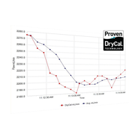
Accurate
DryCal technology measures volumetric gas flow, as well as temperature and pressure, giving you the most accurate results under standardized conditions.
Rugged
Our DryCal system is field-tested and proven reliable in the most demanding environments. Built to laboratory standards, DryCal products deliver portable durability.
Defensible
An annual NIST-traceable calibration by our ISO-accredited facility provides a defensible audit trail and keeps you in compliance with all applicable standards.
Solution Portfolio
DryCal calibrators, software, auditing, and support deliver precision gas flow measurement that fits your application, facility, and requirements.
Annual calibration and repair ensure optimal functioning and aids your auditing process. Our ISO-certified facility offers advanced service and accessory options to give you the customized performance and compliance your application demands.